The major cause of failure of Gas Suppression Systems — such as Inergen®, SAPPHIRE™, IG-541, IG-55 or FM200 is inadequate room sealing. Room Integrity Testing guarantees your fire protection strategy and provides peace of mind. Researcher has found that rooms get leakier with time, usually due to changes in construction, cabling, or services.
Room Integrity Testing is a requirement for all fire protection systems that release a gaseous agent to suppress a fire (a Gas Suppression System). An annual Room Integrity Test is a requirement of Australian Standards AS1851-2012 or International Standards ISO/DIS 14520-1. Read More
Ensuring the establishment and maintenance of robust room integrity is crucial, especially considering the potential repercussions of system failure. While Gas Suppression Systems present a logical solution for rooms housing IT or electronic equipment, it’s essential to note that if the room leaks, the fire suppression agent will escape before effectively controlling the fire. That is why Australian Standard AS1851-2005 “Maintenance of fire protection systems and equipment” requires an Enclosure Integrity Test each year. Insurers and regulatory authorities widely acknowledge the benefits of this, often mandating testing as a requirement.
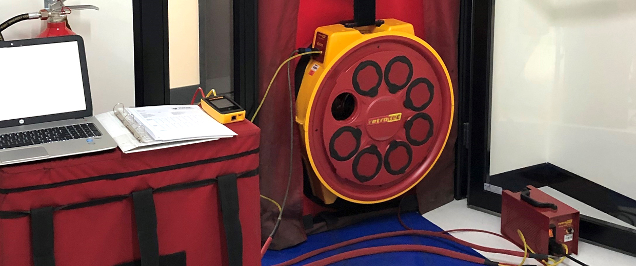
Torvac technicians operate Retrotec Room Integrity Testing equipment with accreditation. We commit to utilizing cutting-edge testing equipment to ensure the delivery of the most accurate information possible. Our testing procedure will grant you the confidence to know that your system is capable of responding to a fire emergency. ou can conveniently schedule the testing of your gaseous protected rooms to minimize any disruption to your business.
The door fan itself merely measures the enclosure leakage area and the pressures that may exist across it. The computer software in conjunction with the DG-700 Hand Held digital pressure I flow gauge does the rest of the simulation and comes up with the prediction. The Retrotec CA2001 software guides the user systematically through each step, ensuring compliance with the relevant NFPA or AS ISO 15420 standards.
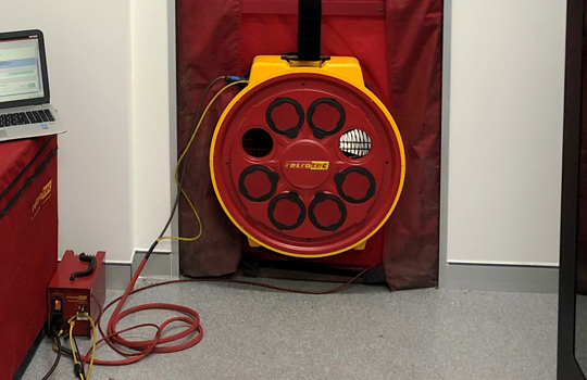
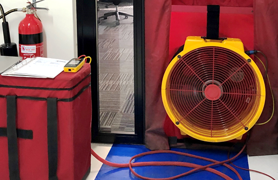
Install the Retrotec Minneapolis Fan Test Unit temporarily in a doorway leading from the protected space to a large open area or outdoors. Adjust the fan speed to achieve a pressure differential between the test room and the surrounding volume. This pressure (usually 1 0 to 15 Pa or 0.04” to 0.06” W.C.) is similar to the steady state pressure (column pressure) exerted by the gaseous extinguishing agent at floor level at the start of a typical 10 minute retention period. The pressure created by the Minneapolis Fan Test Unit causes air to move through leaks at a detectable rate. This makes it very easy to pinpoint exactly where leakage occurs using a chemical smoke.
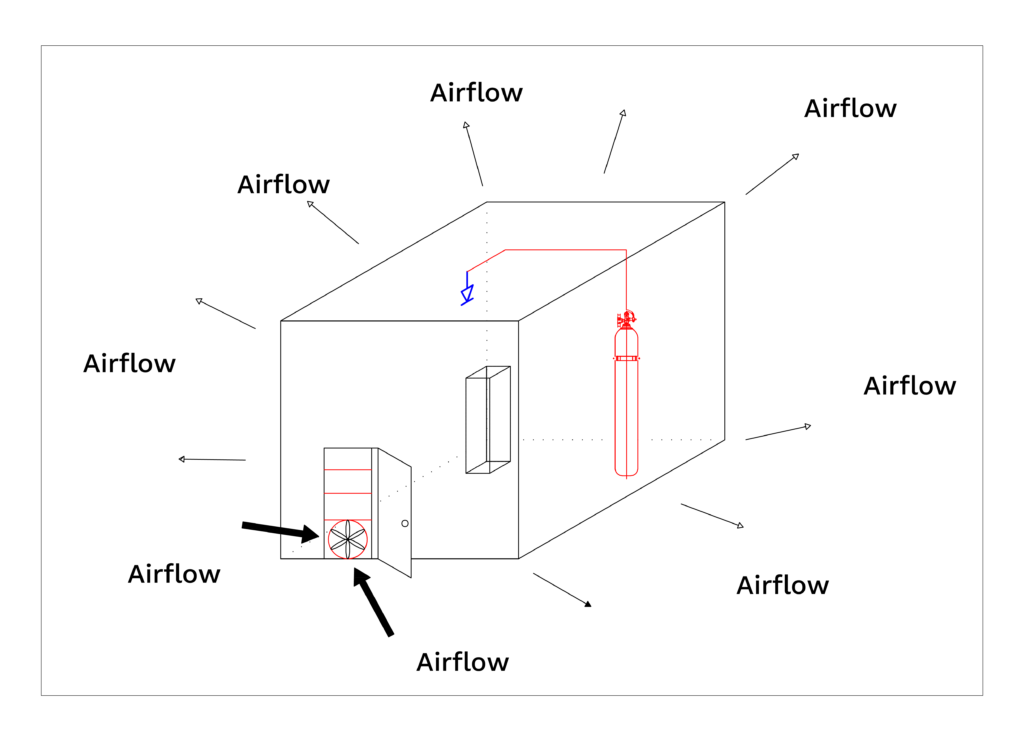
The door fan pressurizes the enclosure to match the pressure exerted by the agent on the floor post-discharge. The flow required to establish this pressure is utilized for calculating the enclosure’s leakage area. The computer software measures both the airflow rate and the pressure generated, subsequently computing the Equivalent Leakage Area (ELA) – representing the total area of all cracks, gaps, and holes in the test room.
To achieve this, the door fan initially expels air from the room (depressurization) and subsequently introduces air into the room (pressurization). The flow pressure across the blower inlet is then converted into flow by the computer software.
The gaseous extinguishing agent mixes violently upon discharge, resulting in a homogeneous mixture. The retention time prediction model disregards pressures generated in the initial seconds of discharge, known as dynamic discharge pressure. This exclusion is due to the brief duration of these pressures and the fact that the concentration formula already accounts for significant loss factors.
The heavier-than-air agent pressing down upon the floor creates a small positive pressure. Flow develops whenever a hole has a pressure difference across it. The greater the pressure and the larger the hole, the greater the agent lost. A small negative pressure will develop at the top of the room that allows a similar volume of air to flow back into the room from leaks at the higher elevations.
When the air-moving equipment in the room shuts off at discharge, the agent mixture usually remains distinct from the air infiltrating through upper leaks. This distinction is specifically identified as the agent/air interface, particularly within the context of the descending interface. As the agent escapes through leaks in the floor and lower wall area, this interface descends. External air typically replaces the agent by infiltrating through leaks in the upper half of the room.
Alternatively, if the air-moving equipment remains operational during the retention period, infiltrating air becomes mixed with the agent, constituting the continual mixing scenario. In this case, the concentration at the floor decays at a similar rate to the concentration near the ceiling. Occasionally, airflow into or out of the room may be induced by other factors such as damper or duct leakage, creating static pressure that expedites the agent’s egress. Typically, this static pressure is eliminated.
The door fan test quantifies total leakage areas and static pressures. Following that, we measure below-ceiling leaks individually, utilizing a flex duct or plastic on the ceiling to mitigate their impact. Other variables such as room volume and heights are easily measured on-site. The model then predicts the time it will take for the descending interface to reach the minimum protected height specified by the Authority Having Jurisdiction or for the concentration to drop to the minimum acceptable percent in the continual mixing case.
The logic for the Room Integrity Testing and survey is to provide assurance to property managers/owners that an appropriate level of protection and a high level of reliability exist for each hazard area.
This report not only provides recommendations for enhancing fire protection but also underscores the significance of effectively managing and maintaining fire protection systems and equipment to ensure their optimal performance and reliability.
Read more about Annual Room Integrity Testing
Torvac Solutions can also carry out Hydrant and Sprinkler Flow Testing
Find out more
Interested in talking to a Room Integrity Testing Specialist?